Project - Fuel Injection with Teensy
This is a link to a video of the EFI project running a small engine.
In the past, I have dabbled in introductory Arduino projects (and by introductory, I mean the very basics - the sorts of projects you can build from an Aduino starter kit). Although I found it interesting, learning physical computing got shelved for a while in favor of pursuing my mechanical engineering education and FSAE. However, I found renewed interest in firmware and computers during my internship with Tesla working on firmware testing. After I learned about Teensy and how powerful it is, I decided to do a personal project that would allow me to exercise my mechanical engineering knowledge while learning about electronics and firmware.
It so happened that I had a Predator 212 small gasoline engine lying around from a prior project (a scratch-built minibike) and experience in internal combustion engines from my time in FSAE. Thus my Teensy EFI conversion project was born.
Hardware
There were a few mechanical engineering problems to solve throughout the project. Broadly speaking, I had to design and fabricate a trigger wheel system to measure crankshaft position, a fuel cell, a fuel pumping and delivery system, and an intake manifold. Since I knew that programming, designing, and building the electronics, and testing the system would take up the bulk of my limited time, I decided to focus on using known parts and designing for manufacturability.
Trigger Wheel System
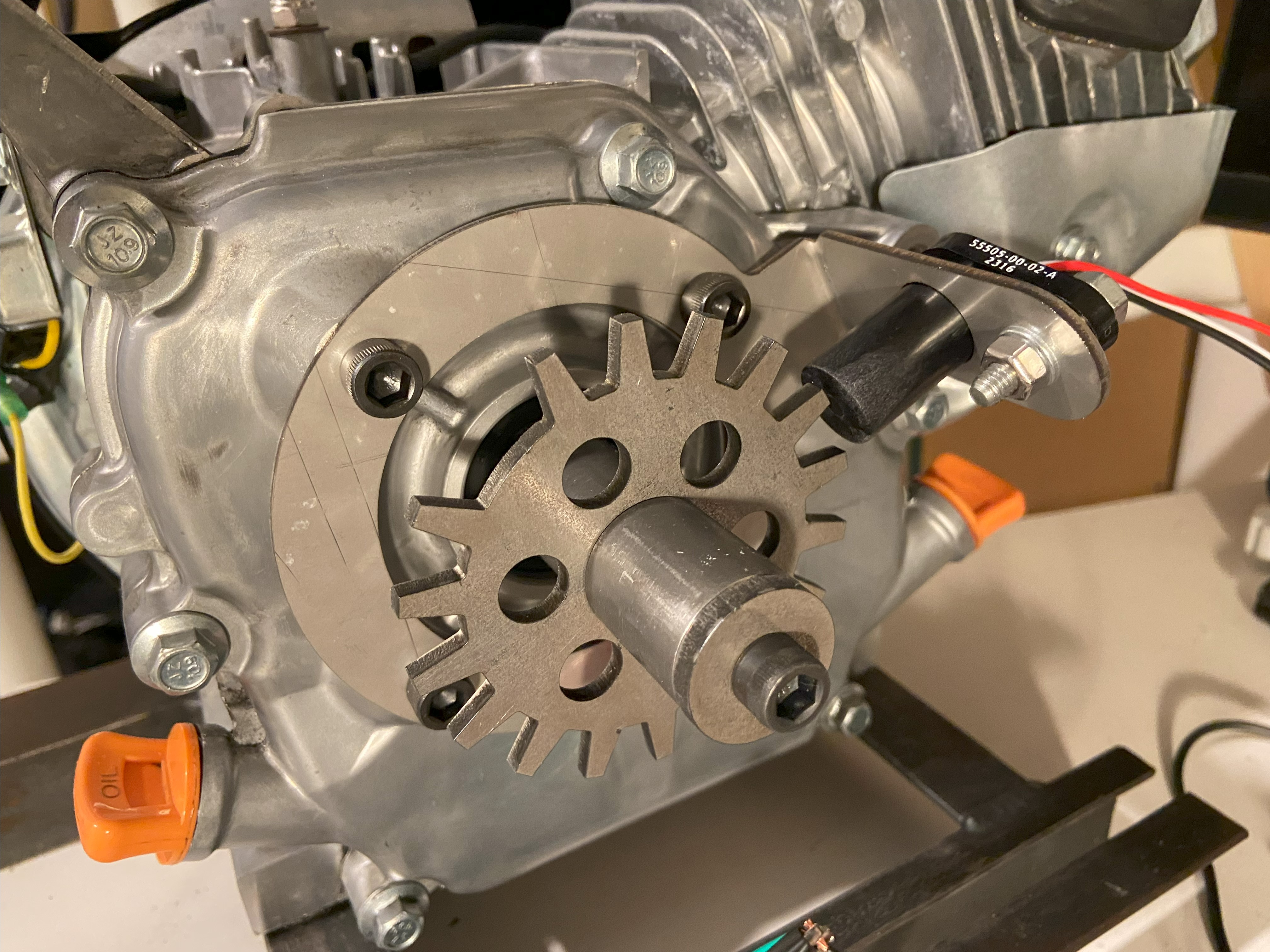
I decided to use a missing-tooth trigger wheel system, which would allow the microcontroller to determine absolute crankshaft position at all times. Although I probably could have gotten away with just engine speed derived from the magneto ignition system, I suspected that accurately timing fuel injection with the intake stroke would make starting the engine easier (especially considering cranking speed and duration is limited by the recoil starter). Also, having accurate crankshaft position would allow expansion of the system later to include microcontroller-timed spark. With this in mind, I designed the trigger wheel system pictured.
The trigger wheel is made of ferrous steel, and the teeth induce a signal in a Hall effect switch to determine crankshaft position. It is keyed to the crankshaft to ensure absolute correlation between tooth and crankshaft position. The Hall effect switch bracket is designed to hold the switch at a constant, small distance away from the trigger wheel. The switch may be shimmed out to adjust the air gap. In hindsight, I really should have used a thicker steel for additional rigidity. The bracket seems to hit a resonance at certain engine speeds, causing the switch to strike the trigger wheel.
I was careful to CAD the trigger wheel parametrically so that its missing tooth and total tooth counts as well as diameter could be easily modified. Indeed, initial testing with an 18-1 revealed that crankshaft acceleration was severe enough during starting to cause crankshaft position sync loss. I was able to design and laser-cut a 24-2 unit within minutes thanks to this foresight, which was much more tolerant of crankshaft acceleration.
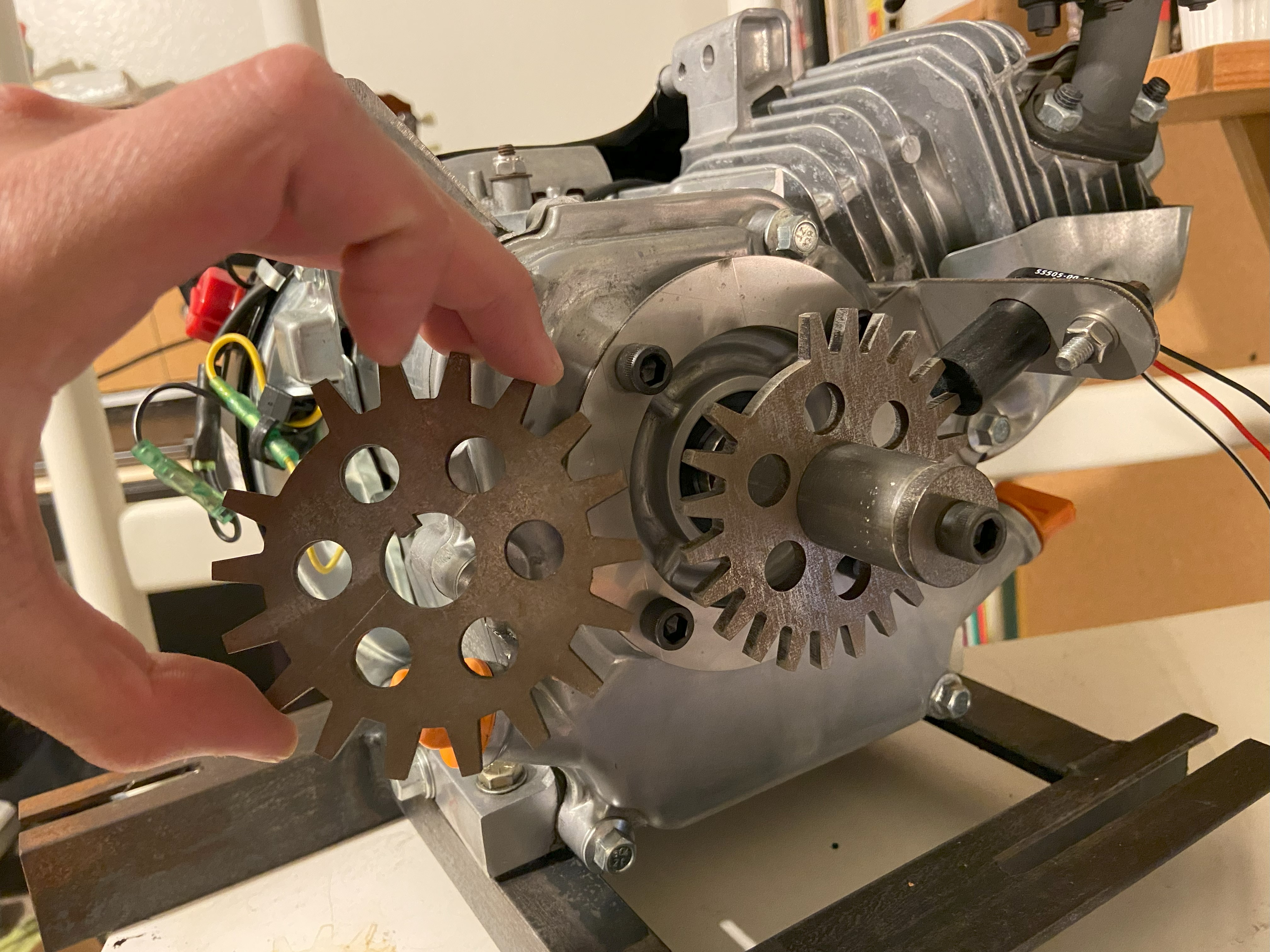 18-1 on the left, 24-2 on the right.
Fuel Cell
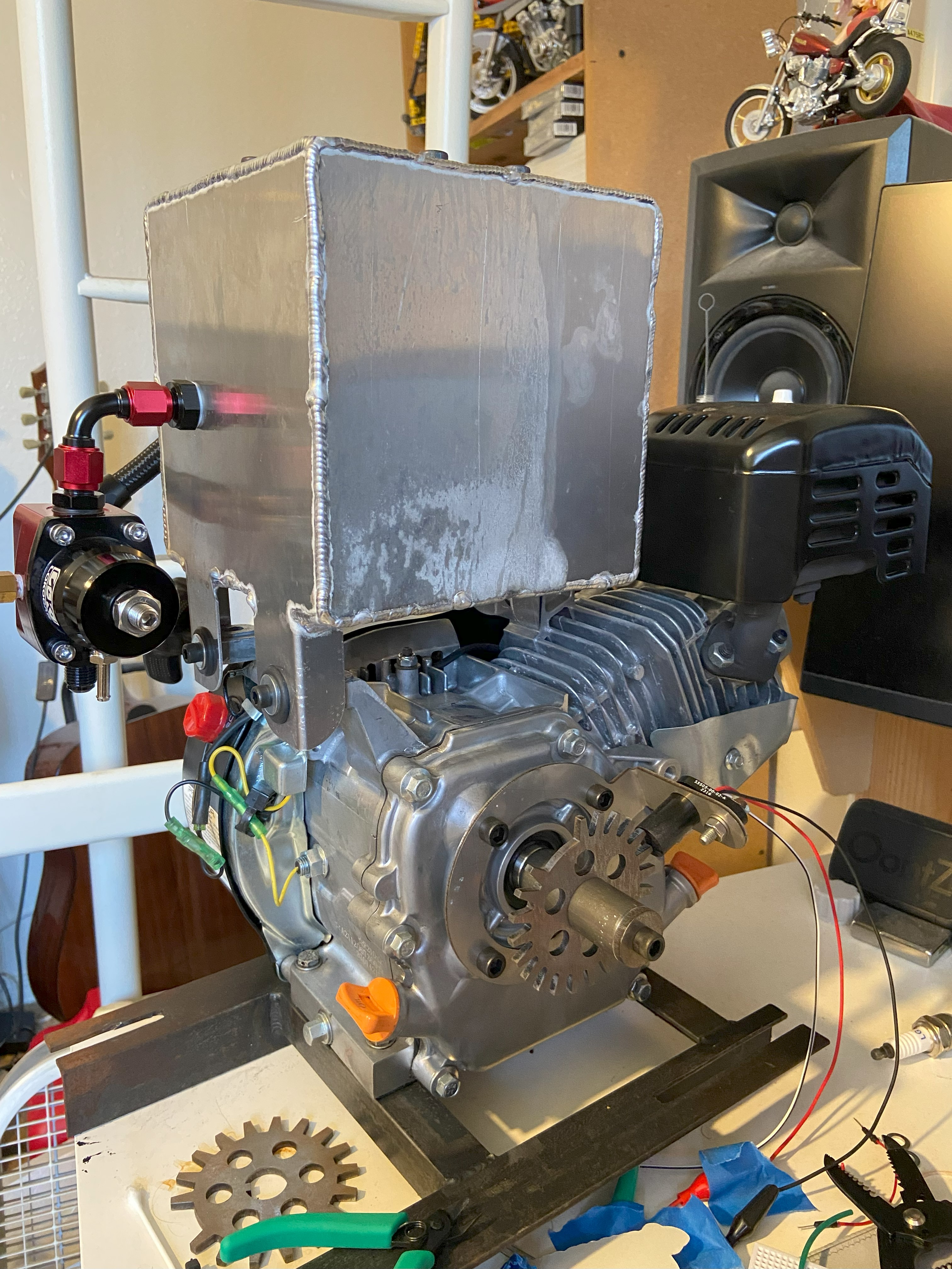
Since I had prior experience designing and fabricating aluminum fuel cells, I decided to take the known approach here. I designed the fuel cell to be laser-cut and welded out of 5052 aluminum. The thickness of the material was limited by my TIG welding skills. It has mounting tabs that interface with the original fuel tank mount points on the engine, as well as a mounting point for the internal fuel pump. An outlet for pressurized fuel and inlet for regulator return interface the fuel cell with external plumbing.
I paid particular attention to the fuel cell mounting points. I wanted the fuel cell to mate seamlessly with the engine even if there was some fabrication and assembly error. Additionally, I wanted the mounting points to absorb some of the engine vibration. Rubber grommets seemed to be the logical choice for satisfying these requirements.
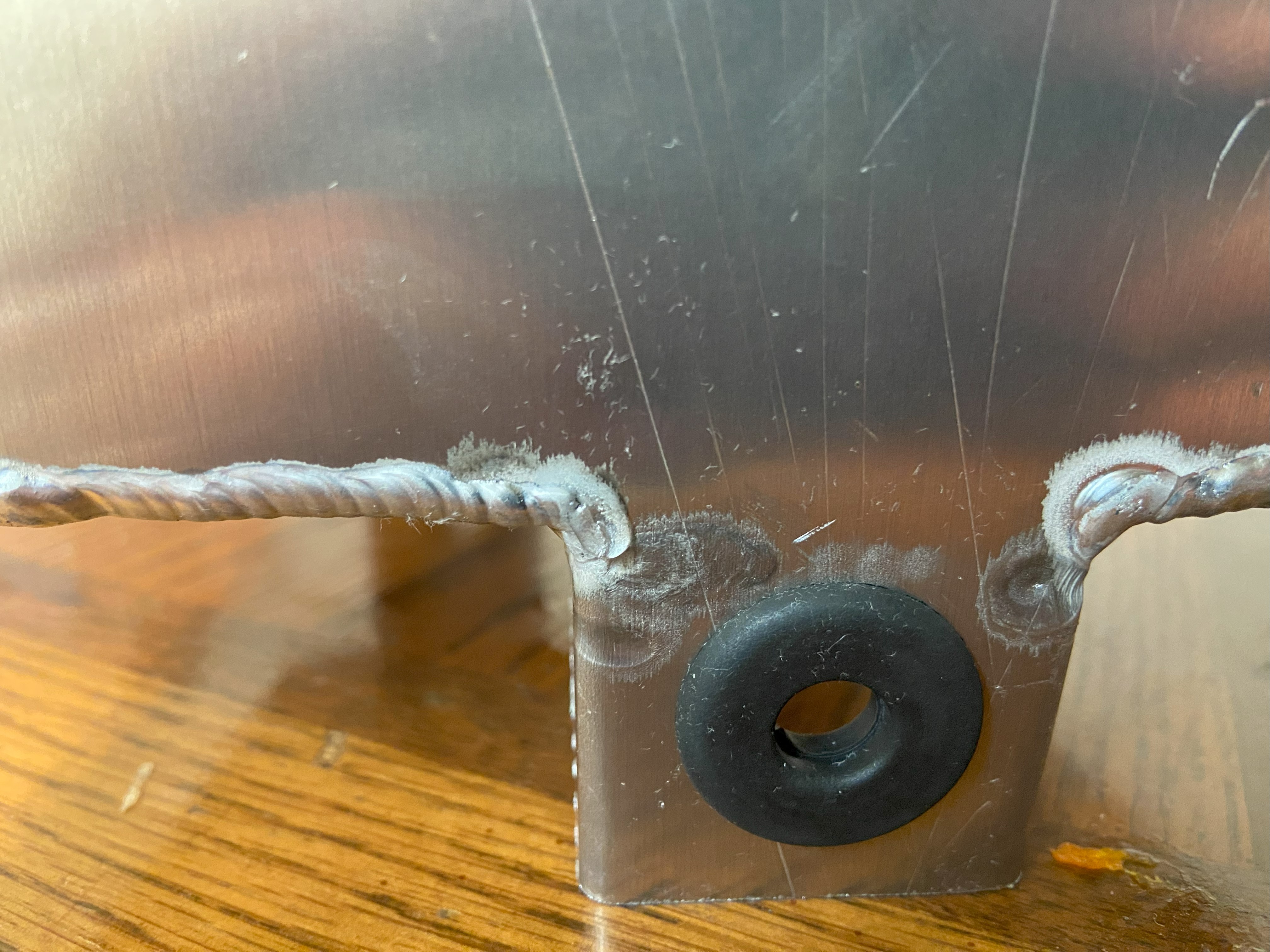 Fuel cell mounting point. A spacer and bolt go through the grommet.
Fuel System
The fuel system is almost a complete copy of that which I designed for our FSAE car, from components to design. A constantly running fuel pump in conjunction with a return-type fuel regulator maintains fuel pressure at a setpoint. The fuel rail and injector are both modified Yamaha FZ6R parts, which were used in our FSAE car. The injector, in its original application, fed a 150 cc cylinder running at up to 11500 RPM. I therefore figured it would be somewhat oversized for the Predator’s 212 cc cylinder cycling at up to 3600 RPM. Were I to expand the scope of the fuel system design, I might have wanted to size the fuel pump more appropriately for the application, as well as include feedback control for the pump using a fuel pressure sensor connected to the unregulated high-pressure plumbing so that the system is not wastefully pumping fuel at all times.
I characterized the fuel injector flow rates by writing a program that sends signals of known pulse length to the injector a set number of times, then measuring the volume of the expelled fuel. I repeated this process for a number of different pulse lengths to determine the relation between pulse length and volumetric flow. The whole process was repeated at both 40 PSI and 50 PSI to study the effect of changing intake manifold pressure on fuel flow. Both the program and the gathered data are in the repo at efi_project/test_injector.
Intake Manifold
The intake manifold has a few functions:
- Draw air from environment.
- Duct air to engine intake port.
- Throttle air intake based on user intent.
- Interface with fuel injector.
- Interface MAP sensor to engine vacuum.
I actually spent quite a bit of time weighing the pros and cons of various manufacturing processes that could be used to form the geometry required to fulfill all these functions. I initially considered machining parts out of aluminum and welding as needed, but this would entail quite a few steps, like machining the fuel rail bracket, turning the injector seat, laser-cutting the intake port flange, and welding it all together. The logical choice seemed to be an additive manufacturing process of some kind. I wanted to avoid FDM 3D printing since the finished products are often not fluid-tight, which would lead to intake leakage and gasoline permeation. Multi jet fusion 3D printing would give me parts with excellent thermal, mechanical, and chemical properties, but was expensive and had a lead time. I therefore settled on UV resin printing, which was a good compromise, providing good fluid tightness and printing speed, with acceptable mechanical and chemical properties.
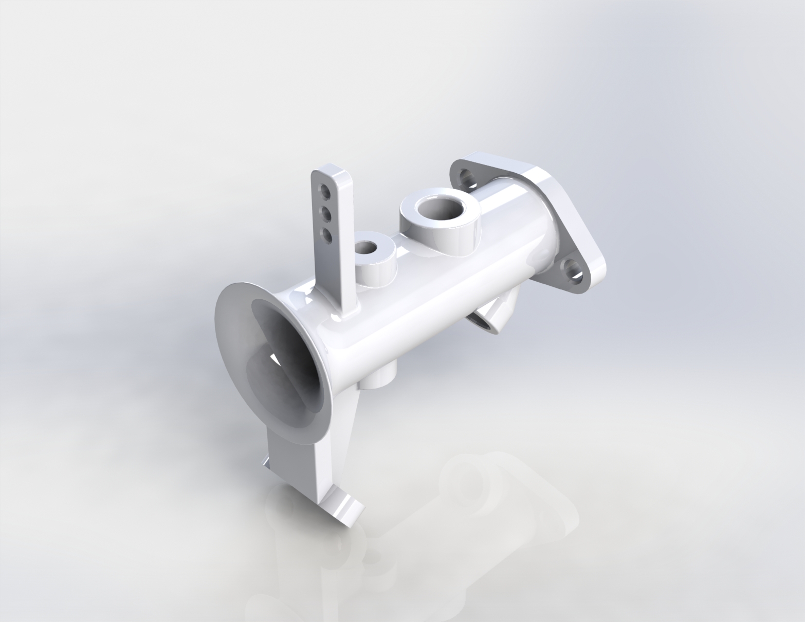
Pictured is the final geometry I settled on. The flared end is the air intake port, and the structure hanging directly below it is the fuel rail bracket. The small hole on the dorsal portion of the intake is for a throttle plate shaft. A similar hole is present on the bottom. The holes are designed to accept press-fit precision bushings, through which the throttle shaft is passed. Once pressed and line-bored, it allowed for smooth shaft rotation while maintaining good air seal. The large port on the dorsal portion of the intake is for the MAP sensor. Note that it comes after the throttle plate in the air flow, allowing engine vacuum measurement. Finally, on the furthest end of the intake, there are the injector seat and intake port flange, interfacing with their respective parts. In practice, I had difficulty with 3D printing the form, with artifacts causing portions of the print to fail. In the end, I had to choose a print attempt with the fewest defects and fill them with putty. This gave a good enough seal for engine operation.
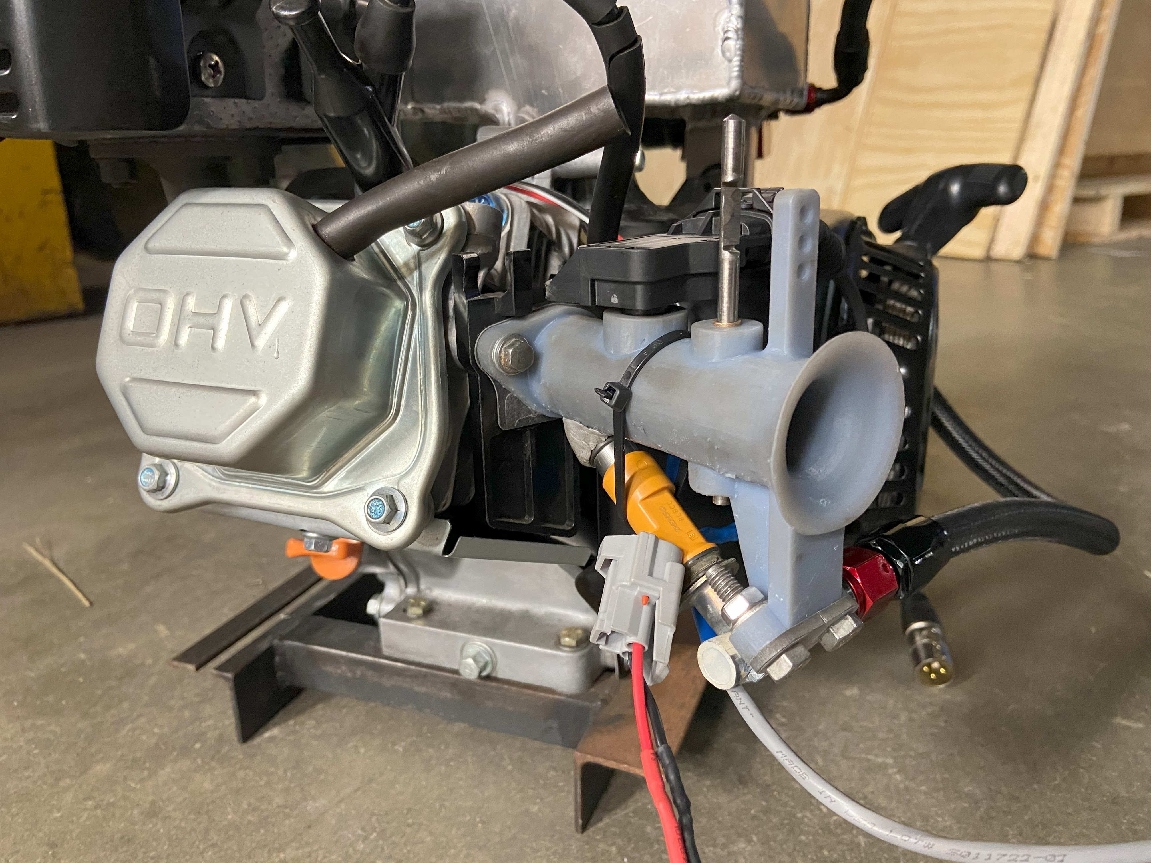 Installed intake system.
Electronics
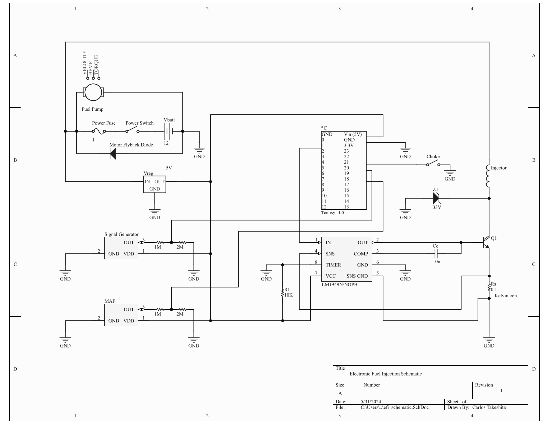 Full schematic of electronics.
The electronic system has to fulfill a number of functions as follows:
- Send crankshaft position sensor and MAP sensor signal to Teensy.
- Get injector signal from Teensy and send it to the injector driver chip.
- Amplify the injector chip output signal to drive the injector.
- Power the fuel pump.
Sensor Suite
I designed the system to run off only two sensor signals - MAP and crankshaft position. For MAP, I chose a 0-5 volt reference signal MAP sensor from Bosch. The fact that it was originally intended for engine applications made it relatively simple to integrate. For crankshaft position, I chose to use a Hall effect switch in conjunction with a trigger wheel. Such a system would be more robust in a dirty environment than an optical sensor, for instance. Also, use of a Hall effect switch rather than a Hall effect sensor meant I would get a clean square wave signal corresponding to trigger tooth detection right out of the box.
Both sensors are excited by a 5 volt supply. The Hall effect switch outputs a square wave between 0 to 4.3 volts, determined experimentally, while the MAP sensor outputs a 0 to 5 volt signal that linearly varies with absolute air pressure. Since Teensy only takes up to 3.3 volts on its input pins, I had to shift the voltage levels down. To accomplish this, I used a voltage divider to drop signal voltage to 2/3 of its original value. I chose a 1 megaohm and 2 megaohm resistor in series for both sensors, which would give the desired voltage drop and provide high impedance between sensor output and ground.
Injector Driver Chip
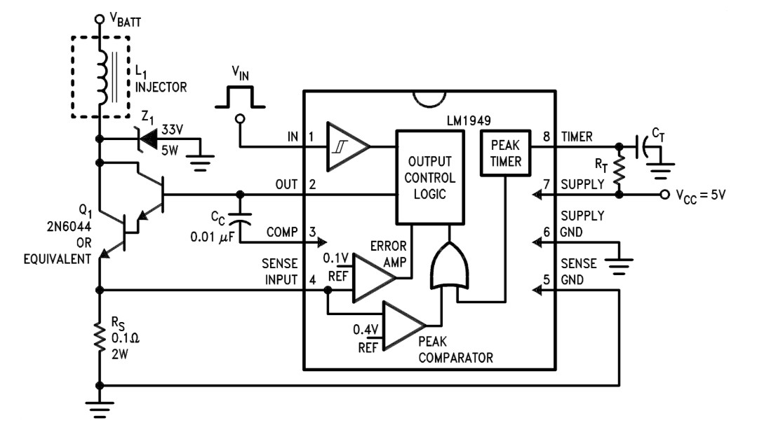 LM1949 configured in a typical application, from datasheet.
Teensy generates a square wave output signal for injector actuation. This signal must be amplified somehow to drive the fuel injector solenoid. At the time I was designing the electronics, I was unsure whether I was going to use a high-impedance or low-impedance injector, so I wanted the driver circuitry to be flexible enough to drive either. Enter the Texas Instruments LM1949. According to the data sheet, LM1949 takes a square wave injector signal from Teensy (at pin 1) and controls injector current with a Darlington pair transistor (base driven by pin 2) by sensing voltage across a precision shunt resistor (pins 4 and 5) in series with the injector. I was careful to interface the sense leads to the resistor with a Kelvin connection to eliminate errors from lead voltage drop. The chip will perform peak-and-hold operation at the start of each pulse up to a time limit, which is set with a resistor-capacitor combination (pin 8). I ended up using a high-impedance injector with no need for peak-and-hold, so I set the time limit to zero by eliminating the capacitor entirely.
Fuel Pump Power
The fuel pump runs constantly when the system is turned on. I was anticipating having to deal with lots of induced electrical noise from what I assume is a simple brushed motor in the fuel pump. However, enclosing the pump in the aluminum fuel cell, twisting wire pairs, and using shielded cable for both sensors seemed to be enough to keep noise down to an acceptable level. I also put a snubber diode in parallel with the fuel pump to absorb flyback current upon shutdown.
Enclosure Packaging and Construction
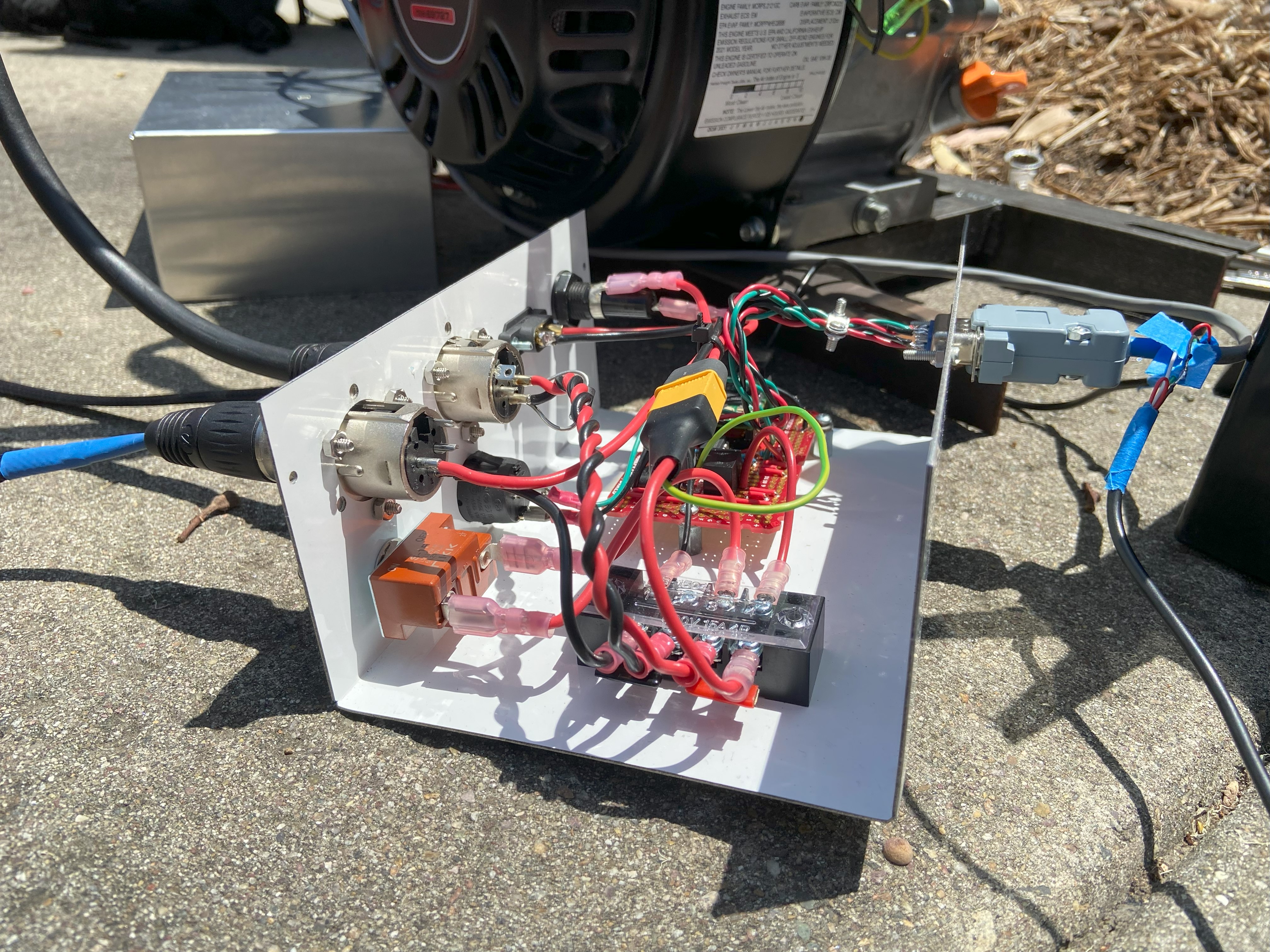
In anticipation of needing to modify and repair various parts of the electronic system while testing, I opted to focus on ease of serviceability and construction for the enclosure. Parts are generally connected with screw and spade terminals where appropriate, and the enclosure is roomy. If I were aiming for a final product, I would place more emphasis on compact packaging, waterproofing with sealed connectors and potting, and vibration resistance by eliminating leads soldered directly to the PCB. To avoid operational mistakes, I exercised a little poka-yoke by using incompatible connectors for each different connection to the box. In particular, the two XLR connectors for battery power in and fuel pump power out are opposite genders. I gave this aspect consideration after killing my first prototype by connecting the battery backwards.
Programming and Testing
Learning to write firmware for Teensy was the main goal of this project, and was thus one of the more time consuming elements. I identified the program’s functional requirements as follows:
- Read crank position sensor signal and interpret to always make crank position available to the program.
- Furthermore, recognize crank position sensor faults and enter fault-safe behavior as needed.
- Initiate fuel injection when crank position reaches a set point.
- Calculate fuel load based on crankshaft speed and MAP sensor signal.
- Actuate fuel injector to achieve desired fuel load.
Writing firmware to reliably fulfill all functional requirements was very challenging, and required learning many new programming concepts. I will explain my logic and subsequent implementation in the following section. The code is available in a public GitHub repository at buffarlos/efi_project. You can also find it on the linked GitHub profile in this site.
Crankshaft Position and Speed
The firmware is dependent first and foremost on crankshaft position and speed to time injection events. Therefore, calculating crankshaft position and speed based on trigger wheel tooth detection is an important function of the program. As the Teensy code currently stands, the main loop detects a trigger wheel tooth when the analog Hall effect switch input signal falls past a set threshold. It will calculate crankshaft position and speed each time the main loop detects a trigger wheel tooth, and extrapolate crankshaft position based on the last calculated crankshaft speed between teeth, up to the position of the next expected tooth. The missing teeth on the trigger wheel indicate to the program when the engine has reached TDC, distinguished by a very long interval between tooth detections. Should the firmware detect a gap where not expected, or not detect a gap where expected, it will set the tooth number variable to 0, which indicates to the rest of the functions in the program that crankshaft sync has been lost, and that all operations should be suspended until crankshaft sync is regained.
In previous versions, the code used an interrupt service routine (ISR) to detect trigger wheel teeth. When the digital Hall effect switch input fell, it triggered an ISR that set a volatile boolean tooth detection flag to true. The main loop function checked the tooth detection flag in an interrupt-safe environment and, if true, set the flag back to false, then performed crankshaft position and speed calculation. Unfortunately, the falling digital signal threshold was not well-defined and the signal was just noisy enough to trigger a false detection every once in a while, leading to crankshaft position sync loss! Since the sync error always occurred during the tooth gap, I initially suspected that crankshaft acceleration was too severe for even a 24-2 configuration, so I tried a 24-4 trigger wheel next. This did not solve the issue, and oscilloscoping the crankshaft position sensor revealed the aforementioned noise. Thus I switched from a digital approach to an analog one, which unfortunately entailed abandoning the ISR-based tooth detection in favor of polling, since there is no interrupt trigger based on analog level threshold. However, this thoroughly corrected the false detection issue, and polling was fast enough to run the engine reliably.
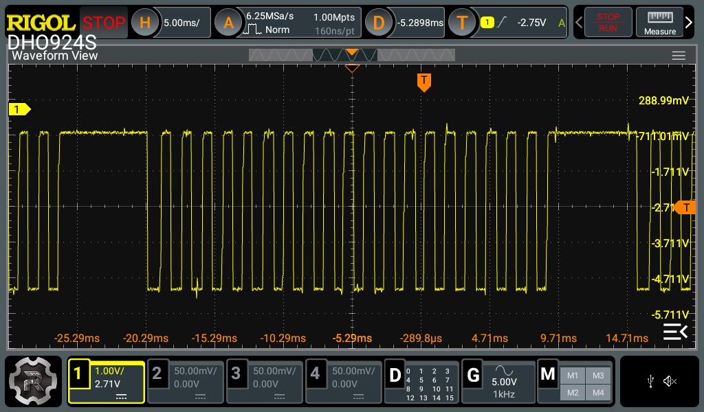 Hall effect switch waveform, 24-4 trigger wheel. Note the gap in the square wave where the missing teeth are, and the noise in the signal.
Fuel Injection
When the crankshaft position passes a set fuel injection point, the fuel injection sequence begins, so long as the tooth number variable is not 0 (indicating crankshaft position sync loss) and engine speed is below redline. The fuel injection sequence first gathers MAP signal and crankshaft speed, then passes them to the following injection time calculation function:
1
2
3
4
5
6
7
8
9
10
11
12
13
14
15
16
17
18
19
20
21
22
23
24
25
26
27
28
29
30
31
32
33
34
35
36
37
38
39
40
41
42
43
44
45
46
47
48
49
50
51
52
53
54
55
56
57
58
59
60
61
const float ENRICHMENT_FACTOR = 1.5; // Multiply injector pulse length by this amount so long as choke switch is on.
const float DEAD_TIME = 1000.0; // Minimum injector pulse length to open injector, in microseconds.
const unsigned long ONE_HUNDRED_PCT_VE_PULSE = 8694; // Stoichiometric fuel load pulse at 100% VE minus dead time, in microseconds.

// ------------------------- Injection pulse length calculation function -------------------------
unsigned long Injection_Time_Calculation(float Crankshaft_Speed, float MAP) {
  // Takes current crankshaft speed and MAP, and calculates interpolated injection time based on VE table.
  // VE Table Constants.
  const int VE_Table_Speed_Points = 8; // Number of linearly spaced tabulated crankshaft speed points in VE table.
  const int VE_Table_MAP_Points = 8; // Number of linearly spaced tabulated MAP points in VE table.
  const float VE_Table_Minimum_Speed = 0.003; // Minimum tabulated crankshaft speed in VE table, in degrees per microsecond.
  const float VE_Table_Maximum_Speed = 0.024; // Maximum tabulated crankshaft speed in VE table, in degrees per microsecond.
  const float VE_Table_Speed_Step = (VE_Table_Maximum_Speed - VE_Table_Minimum_Speed)/(VE_Table_Speed_Points - 1); // Interval between tabulated crankshaft speed values.
  const float VE_Table_Minimum_MAP = 20.0; // Minimum tabulated MAP in VE table, in kPa.
  const float VE_Table_Maximum_MAP = 120.0; // Minimum tabulated MAP in VE table, in kPa.
  const float VE_Table_MAP_Step = (VE_Table_Maximum_MAP - VE_Table_Minimum_MAP)/(VE_Table_MAP_Points - 1); // Interval between tabulated MAP values.
  float VE_Table[VE_Table_MAP_Points][VE_Table_Speed_Points] = {
    {0.3, 0.3, 0.3, 0.3, 0.4, 0.4, 0.3, 0.3}, // 20.0 kPa
    {0.4, 0.4, 0.4, 0.5, 0.5, 0.5, 0.5, 0.4}, // 34.3 kPa
    {0.5, 0.6, 0.6, 0.7, 0.7, 0.7, 0.7, 0.7}, // 48.6 kPa
    {0.6, 0.6, 0.6, 0.7, 0.7, 0.8, 0.8, 0.7}, // 62.9 kPa
    {0.6, 0.7, 0.7, 0.7, 0.8, 0.8, 0.8, 0.8}, // 77.1 kPa
    {0.7, 0.7, 0.7, 0.8, 0.8, 0.8, 0.8, 0.8}, // 91.4 kPa
    {0.8, 0.8, 0.8, 0.8, 0.8, 0.9, 0.9, 0.8}, // 105.7 kPa
    {0.8, 0.8, 0.9, 0.9, 0.9, 0.9, 0.9, 0.8}  // 120.0 kPa
  // 500  1000 1500 2000 2500 3000 3500 4000
  }; // Main VE table.
  float Start_VE_Table[1][VE_Table_MAP_Points] = {
    {0.7, 0.7, 0.7, 0.8, 0.8, 0.8, 0.9, 0.9}
  }; // Startup regime VE table.
  int Lower_MAP_Index = max(0, min(VE_Table_MAP_Points - 2, (int)((MAP - VE_Table_Minimum_MAP)/VE_Table_MAP_Step))); // Index of tabulated MAP below measured MAP.
  int Upper_MAP_Index = Lower_MAP_Index + 1; // Index of tabulated MAP above measured MAP.
  float Interpolated_VE; // Interpolated VE based on VE table.
  if (Crankshaft_Speed < VE_Table_Minimum_Speed) {
    Interpolated_VE = Interpolation(MAP, (Lower_MAP_Index*VE_Table_MAP_Step + VE_Table_Minimum_MAP), (Upper_MAP_Index*VE_Table_MAP_Step + VE_Table_Minimum_MAP),
      Start_VE_Table[0][Lower_MAP_Index], Start_VE_Table[0][Upper_MAP_Index]);
  }
  else {
    int Lower_Speed_Index = max(0, min(VE_Table_Speed_Points - 2, (int)((Crankshaft_Speed - VE_Table_Minimum_Speed)/VE_Table_Speed_Step))); // Index of tabulated crankshaft speed below measured crankshaft speed.
    int Upper_Speed_Index = Lower_Speed_Index + 1; // Index of tabulated crankshaft speed above measured crankshaft speed.
    Interpolated_VE = Interpolation(Crankshaft_Speed, (Lower_Speed_Index*VE_Table_Speed_Step + VE_Table_Minimum_Speed), (Upper_Speed_Index*VE_Table_Speed_Step + VE_Table_Minimum_Speed),
      Interpolation(MAP, (Lower_MAP_Index*VE_Table_MAP_Step + VE_Table_Minimum_MAP), (Upper_MAP_Index*VE_Table_MAP_Step + VE_Table_Minimum_MAP),
        VE_Table[Lower_MAP_Index][Lower_Speed_Index], VE_Table[Lower_MAP_Index][Upper_Speed_Index]),
      Interpolation(MAP, (Lower_MAP_Index*VE_Table_MAP_Step + VE_Table_Minimum_MAP), (Upper_MAP_Index*VE_Table_MAP_Step + VE_Table_Minimum_MAP),
        VE_Table[Upper_MAP_Index][Lower_Speed_Index], VE_Table[Upper_MAP_Index][Upper_Speed_Index]));
  }
  // Translate VE to an injector pulse length.
  float Injection_Time = DEAD_TIME + (ONE_HUNDRED_PCT_VE_PULSE*Interpolated_VE);
  if (digitalRead(Choke_Pin) == LOW) {
    Injection_Time = Injection_Time*ENRICHMENT_FACTOR;
  }
  Injection_Time = 0.5*Injection_Time;
  int Int_Injection_Time = static_cast<int>(Injection_Time);
  return Int_Injection_Time;
}

// ------------------------- Interpolation function -------------------------
float Interpolation(float x, float xl, float xu, float yl, float yu) {
  // Performs linear interpolation between input values yl and yu.
  return yl + (yu - yl)*(x - xl)/(xu - xl);
}
In a nutshell, the injection time calculation function uses the received crankshaft speed and MAP data to interpolate a volumetric efficiency (VE) from the VE table. It then multiplies the injector pulse length required for a 100% VE intake cycle by the VE, adds injector dead time, and returns the final value to the main loop. Finally, the main loop sends a signal to the injector driver chip for the appropriate length of time. Note that the main loop will compare the two most recently measured MAP values and send the lower value of the two to the injection time calculation function to ensure MAP is only read on intake strokes. The multiplication by 0.5 in line 52 ensures only half the calculated fuel load is injected per engine cycle to account for the fact there are two engine cycles per intake event.
The program can also detect whether a physical choke switch on the control unit is turned on as seen in line 49, and multiply the injection time interval by an enrichment factor to assist starting and cold operation, which proved invaluable.
Fuel Injector Flow Characterization
Note that 100% VE pulse is a constant set to 8694 microseconds. This is a rough value calculated based on the ideal gas law and empirical injector flow data. The first order of business in obtaining this value was finding how much fuel the engine requires for a 100% VE intake cycle. A little bit of chemistry is required for this calculation. The stoichiometric combustion of octane, a major constituent of gasoline, is given by the following formula:
\[ 2C_{8}H_{18}+25O_{2}=16CO_{2}+18H_{2}O \]
Accounting for the fact that air is about 21% oxygen and 79% nitrogen and other compounds, this gives a mass air-fuel-ratio (AFR) of about 15:1. However, it is well-known that gasoline is a mix of a huge number of petrochemicals which, in aggregate, gives it an AFR of 14.7:1. This was the value off which I based my calculations. Next, I found the volume of air combusted during a 100% VE intake cycle. Assuming perfect scavenging and cylinder filling along with negligible fuel volume, I used the following equation:
\[ CR={V_{d}+V_{c} \over V_{c}} \]
where \(V_{d}\) is displacement, \(V_{c}\) is clearance volume, and \(CR\) is compression ratio. Using the known displacement of 212 cc and compression ratio of 9.5:1, I solved for \(V_{c}\), after which I calculated the volume of the air charge to be \(V_{c}+V_{d}=237cc\). The molar mass of dry air is 28.96 grams per mole, which gave me all the parameters for the ideal gas equation. Assuming ambient pressure of 101000 pascals, volume of 237 cc, and ambient temperature of 297 K, I calculated that an air charge weighs \(0.281g\). I divided this result by the AFR of 14.7 to get \(1.910 \times 10^{-2}g\) of fuel which, based on an assumed gasoline density of \(0.720{g \over cm^{3}}\), is \(2.652 \times 10^{-2}cm^{3}\). In conjunction with empirical flow data gathered by bench flowing the injectors, I calculated the 100% VE pulse length. My partner, Andrew Du gathered and plotted the following injector flow data, available in the Git repository in efi_project/test_injector.
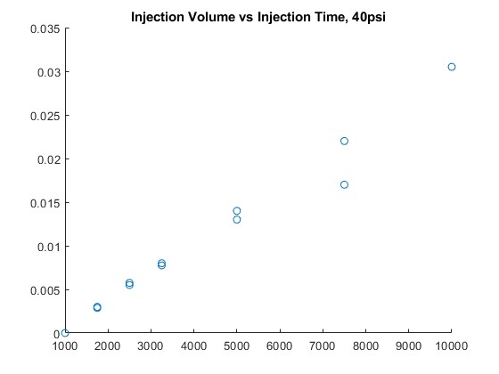 X-axis pulse length in microseconds, y-axis injection volume per cycle in cc. The x-intercept indicates an injector dead-time of 1000 microseconds. The outlier at 7500 microseconds is an erroneous graduated cylinder reading.
Further Testing and Features and Conclusion
The scope of this project was quite a bit more limited than I would have liked, due to time constraints. My greatest regret is not being able to properly tune the VE table at all. In its current state, it is pure guesswork - only good enough to run the engine very rich. Much of the VE table cannot even be tested in the current hardware configuration on account of the fact a load cannot be placed on the engine. Given sufficient time and resources, I would have liked to install an O2 sensor and tune VE for all MAP and engine speed combinations, at least in-vehicle on the minibike, if not on a proper dynamometer. Also, such an O2 sensor would have also allowed for closed-loop idle mix control, which might have been beneficial for stable idle while subjected to environmental disturbances, such as air composition and temperature.
The project was, in my eyes, a success, in that I was able to integrate functional mechanical and electronic systems with a microcontroller, and learn a great deal about electronics and firmware writing along the way. The fact that the engine ran and idled well was a wonderfully satisfying result and a tangible measure of success.
Acknowledgements
I would like to thank my dear friend Andrew Du for the invaluable programming advice and code review he provided, as well as his assistance in testing and enthusiasm. I also extend my thanks to Ben Zhang for his insight in troubleshooting crankshaft position sensor noise. I would have never squashed that bug without his assistance.