Project - FSAE Engine Air Intake
Perhaps the magnum opus of my stint as powertrain lead of my FSAE team, Triton Racing, my engine air intake project gave me the opportunity to experience all aspects of a system’s design, from conception, design, manufacturing, to testing. The resulting design contributed to my team’s all-time top finish of 4th place at the Michigan FSAE competition of 2023.
Design Scope: Learning from Past Mistakes
My first FSAE competition was Michigan 2022. Since I was a new member in Fall 2021, I was not very involved in that year’s design cycle, and mostly experienced testing before competition. Through helping with testing and maintaining that season’s car, I came to observe a number of weaknesses in the intake system. The system’s intake runners were modified stock throttle bodies, to ease interfacing with the engine head. Although this did indeed make installation simple and eliminate the need for time-consuming design, it required challenging aluminum welding fabrication, which always led to porosity and subsequent leaks. It was also heavy, since the throttle body included features meant to interface with sensors and throttle plates that were not present in our application. Also, the intake plenum was a 3D-printed piece separate from the intake runners, which meant the two pieces had to be mated with fasteners and sealed. The sealing never worked perfectly, which made engine tuning virtually impossible owing to difficulty achieving stable engine vacuum. Thus I formed the following design goals for the 2023 car’s intake system:
- Design our own intake runners which interface directly with the engine intake boots, for weight reduction and ease of manufacturing.
- Make the intake runners and plenum integral, to avoid the risk of leakage entirely.
- Focus on manufacturability, ease of installation, and good sealing.
- Drivability. Ensure the resulting system is conducive to assisting drivers in minimizing lap time.
Design Phase
Overview
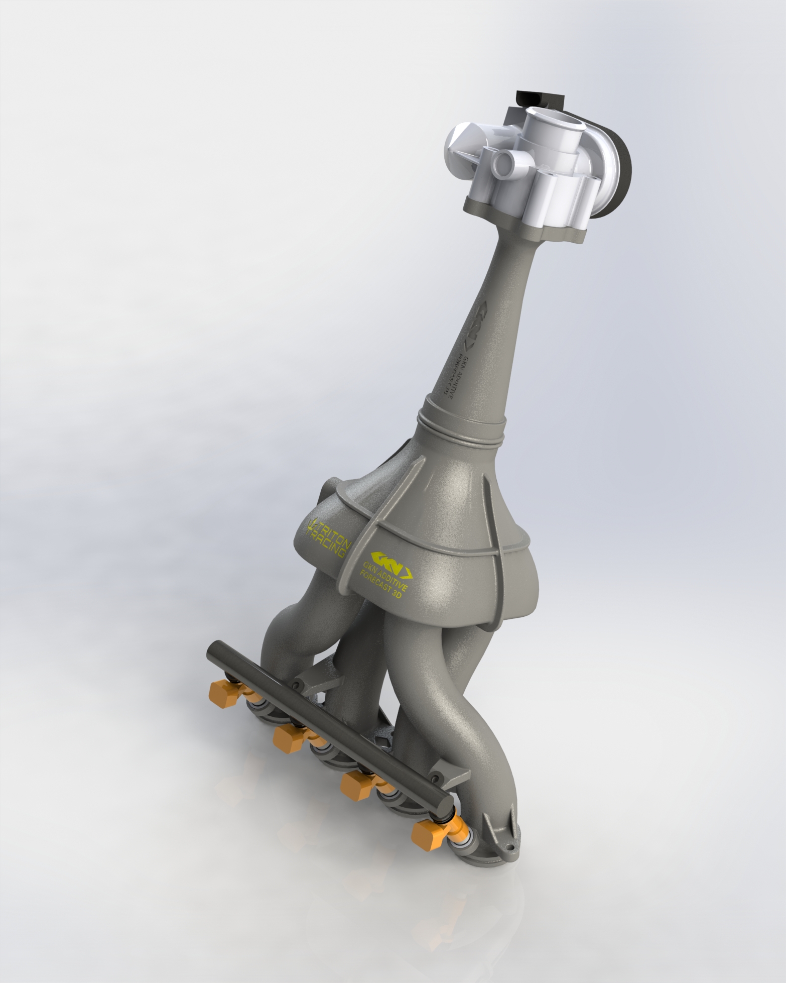
The intake system was designed as a monolithic piece to be 3D printed on Hewlett-Packard’s Multi Jet Fusion (MJF) process using glass-filled nylon 12. The material was chosen for its gasoline resistance and superior stiffness, particularly at high temperatures, compared to non-glass-filled nylon 12. Parameters including intake runner length and diameter and plenum volume were determined using a combination of 1D gas flow simulation and empirical data from the previous year’s competition. One unique design feature is the recessed intake runners. In order to satisfy the intake runner length parameter while fitting the whole system into the required dimensions, the intake runners for cylinders 2 and 3 extend into the plenum itself. Since excellent sealing was a stated goal of the design, the fuel injector seats are smooth machined aluminum inserts designed to be bonded into recesses in the 3D printed piece. This gives the injector seals smooth surfaces to mate with, rather than the rough surfaces on the 3D printed part.
Parametric Design
The design phase of the intake system was characterized by frequent changes in the systems with which it would integrate, as well as fluctuating parameters of the intake system itself. It was not too uncommon to get new intake runner length and plenum volume parameters, then receive a change in chassis envelope or engine placement that would require a change in intake system design soon after. It quickly became apparent that doing extensive redesign each time something changed was a waste of time and energy. Therefore, I designed the system parametrically, setting only the engine intake port interface in stone and making dimensions such as runner length and diameter and plenum volume easily adjustable. I also made the intake plenum position and angle relative to the engine head as adjustable as possible to accommodate changes in envelope. By the time chassis envelope, engine position and intake system parameters were finalized, I had a good workflow in place, allowing me to generate a design ready for manufacturing soon after.
FEA of System Under Vacuum
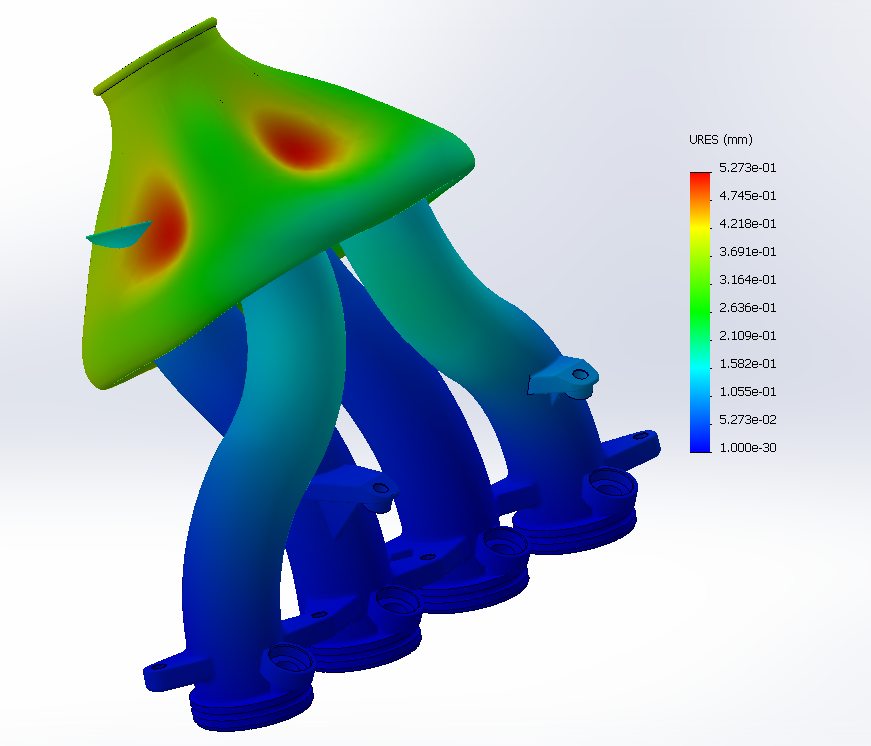
One iteration of the preceding year’s design had stiffness issues, causing the plenum to collapse under high engine vacuum. There was an unsuccessful attempt to mitigate the flexing with internal aluminum ribs, and I wished to avoid the same situation for my year, so I did a little FEA simulation. Pictured is an FEA solution of my system under 1 atmosphere vacuum (worst case). Using the geometry I designed and material properties provided by the 3D printing service, I determined that the plenum would deflect minimally under worst-case engine vacuum. The isometric nature of MJF glass-filled nylon 12 aided in simplifying the problem. No significant deflection was observed in the final design during testing.
Intake Runner Length
When wave tuning intake runners to provide inspired air charge, the designer must typically choose a single engine speed at which to provide boost. This corresponds to a certain intake runner length. Outside this narrow frequency band, the intake runners will not resonate so as to increase air pressure at the intake valve. I considered a number of strategies for determining intake runner length.
Arbitrarily choosing an engine speed, perhaps near redline or driver-specified, might allow the intake to increase maximum power or maximum torque at the driver-specified RPM, respectively. Intake runner length can then be chosen based on simple Helmholtz resonance calculations. There are two issues with this approach. The chosen engine speed in either scenario is arbitrary, and is not well-justified. Also, such a simple calculation would fail to account for the gas dynamics presented by the intake restrictor and plenum.
A partial solution to the issues presented by the preceding method is using 1D gas flow simulation, in our case Ricardo Wave. My colleague Landon Davis developed a model of our powertrain in Ricardo Wave and did all the simulation. Using Ricardo Wave would allow us to consider plenum volume and intake runner length and diameter in combination, from which the simulation could generate a torque curve across the entire rev range. Sweeping the simulation across ranges of intake system parameters would give a large number of torque curves to choose from, which we might filter based on the merit of peak power and high torque at desirable engine speeds. However, this method gives a huge number of solutions to sift through, and the choice is still arbitrary.
This is where my colleague, Andrew Du’s experience shined through. Since we had telemetry from the preceding year’s competition including engine speed and throttle position during endurance, he decided to use that data combined with the Ricardo Wave simulation solutions to choose the optimal parameters. In a nutshell, Andrew generated a histogram, with the x-axis representing engine speed and the y-axis representing the normalized time spent at each RPM bin while above 70% throttle. He then multiplied each Ricardo Wave solution by the aforementioned histogram, and calculated the area under the resulting curves. The curve with the highest described area could be expected to deliver the most torque at the engine speeds where the drivers were historically found to be on-throttle. I felt that this solution would most directly support the stated goal of drivability, and chose to incorporate the derived parameters in my design.
Manufacturing and Assembly
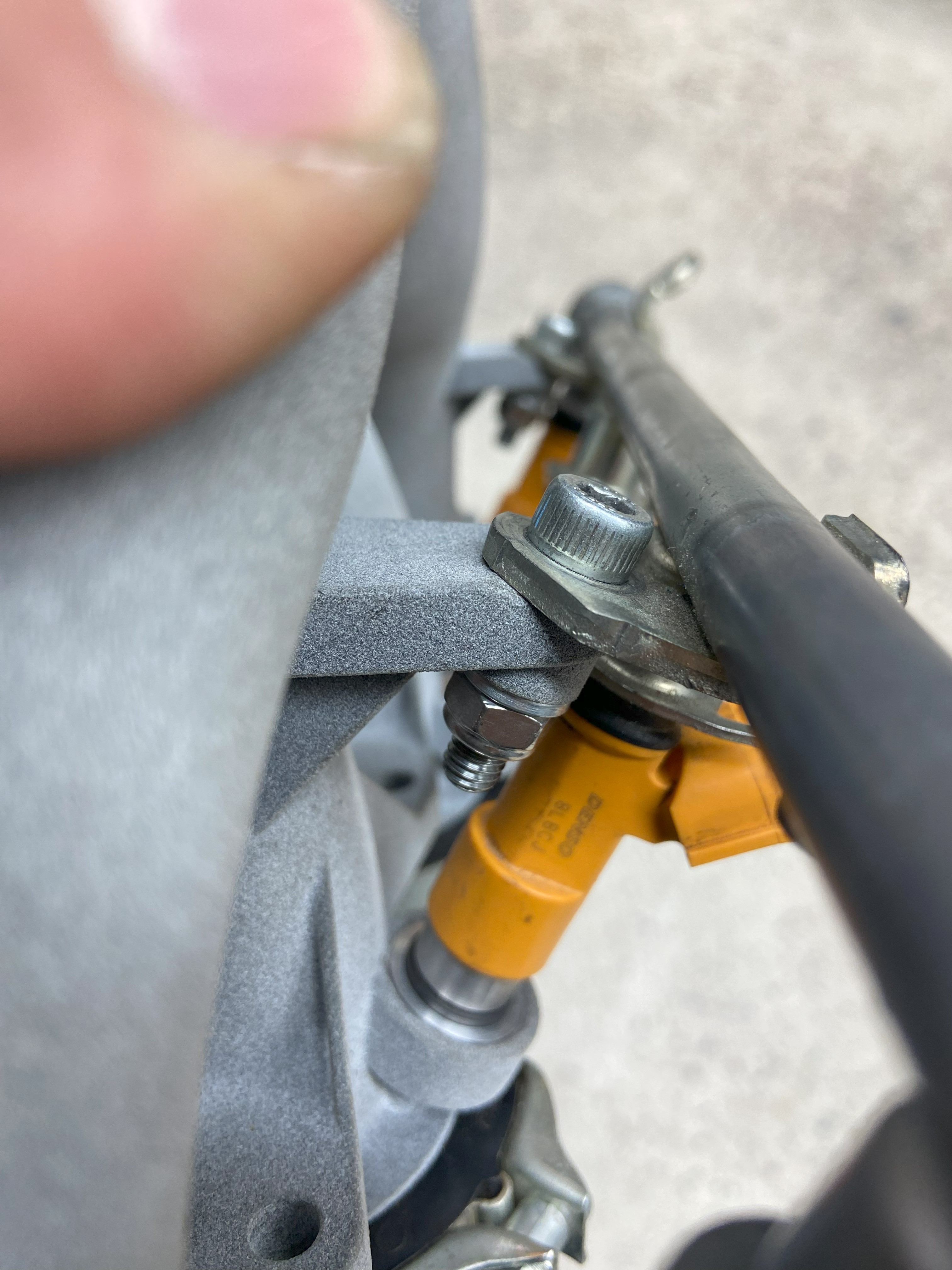
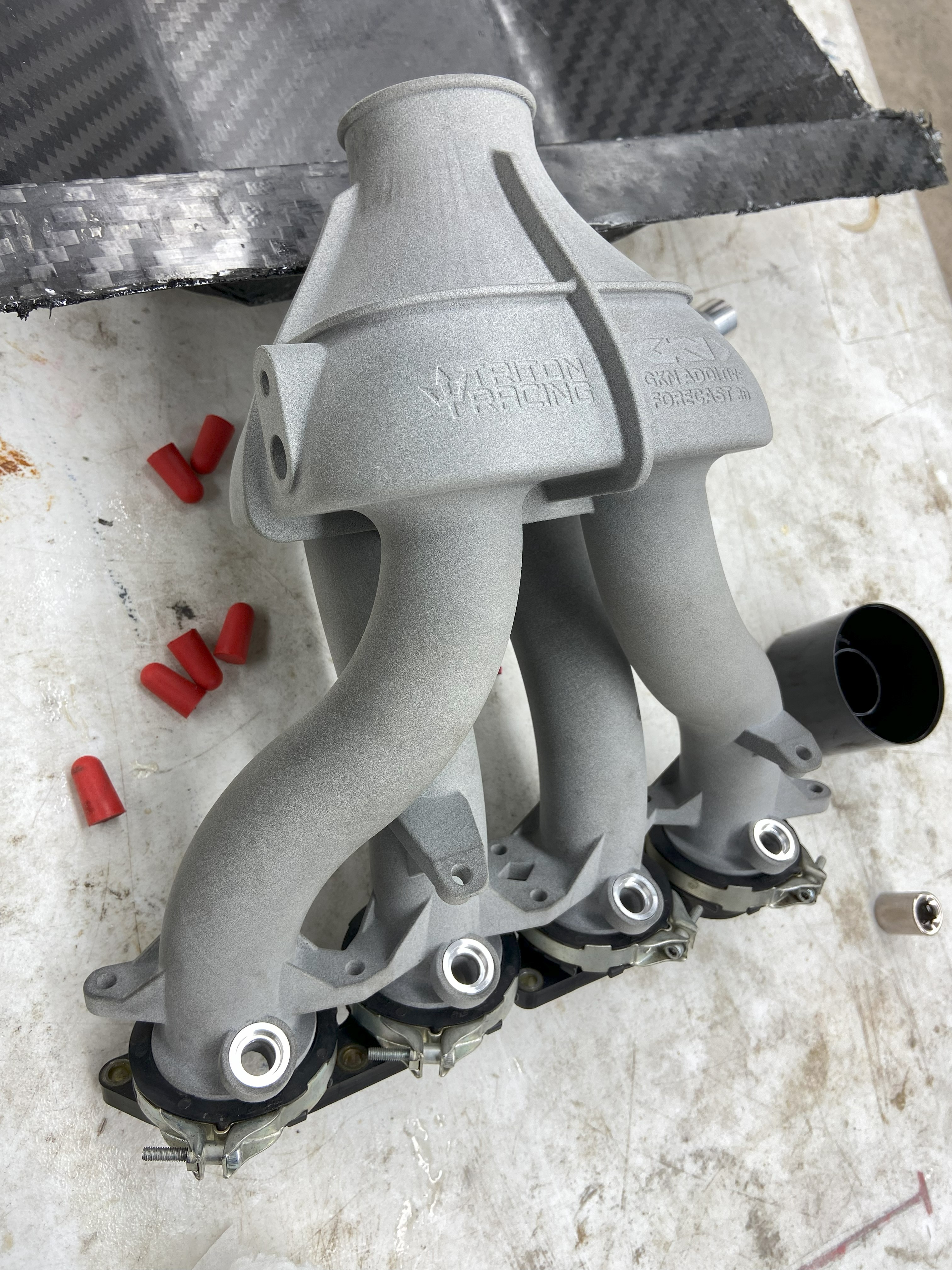
The 3D printed parts we received were of excellent quality and dimensions. The intake boots and fuel system interfaced perfectly with the parts I designed. To ease assembly in the cramped engine bay, I chose to switch from the stock bolt-mounting system to studs, which kept the intake system aligned as the fasteners were tightened, and put the fastener heads in a less cramped place.
Validation
My team had an in-house designed and manufactured water brake dynamometer, which was the result of a senior project from a few years ago. It had never been used for its intended application until the 2023 season. Landon and I worked to complete the system and prepare it for use with our powertrain. The work included replumbing the water brake, calibrating the load cell, installing safety equipment, and lots of electronics troubleshooting. Once the engine was running and the water brake was operational, I developed the workflow for tuning volumetric efficiency tables, after which Landon finished tuning. The resulting system was competitive and, as an added bonus, scored third overall at competition in fuel efficiency.
Areas for Improvement and Conclusion
I felt that the effectiveness of my design was validated by the exhilarating result at competition. The system produced achieved the stated goals, and I was proud of the fit and finish. On top of that, weight savings over the last season’s system was a little over a kilogram. However, I still felt that there were weaknesses in the process and areas for improvement. First, the Ricardo Wave model was not validated against experimental data or even 3D CFD. I regret not doing more in this area. Second, the manual operation of the water brake dynamometer meant that engine load was not precisely controlled, and it was impossible to hold engine speed at a set point. I would have liked to implement electronically controlled inlet and outlet valves to automatically control flow rate and water level so that steady state operation could be achieved.